Make Every Part Count: Part Design Recommendations
The downloadable table contains general part design recommendations. These are intended as “best practice” guidelines applicable for all molding compounds. Successful commercial parts have been designed and produced that are exceptions to these guidelines. Contact a Bakelite Synthetics Bakelite® technical representative to determine what is possible for your specific application.
Wall Section Thickness
Recommended primary structure thickness:
0.08” (2 mm) to 0.24” (6 mm) with variations within ±10 – 25%.
The recommended range in wall section thickness is suggested as a practical design range that balances the ability to fill parts on the low end with minimizing cure time on the upper end. What is achievable or practical in practice is highly dependent on the type of engineering thermoset used and the requirements of the part.
Thin wall sections can be difficult to properly fill, especially if the part has deep, intricate features and the material in use is glass fiber reinforced. Thick wall sections fill easily, but greatly extend cure times due to the increase in mass. Both extremes run the risk of voids due to trapped gasses and internal shrink stresses, which can result in warpage.
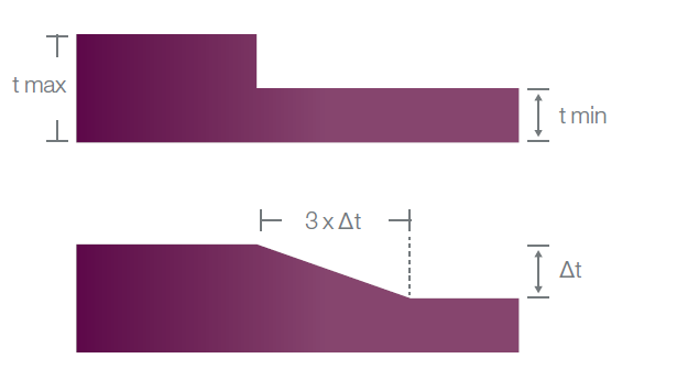
Thickness transitions should be kept to a minimum. Where necessary, they should be smooth. Suggested practice is to keep variations in the primary structure thickness to ±10 – 25% and to transition from thick to thin over a distance equal to three times the thickness change as illustrated in Figure.
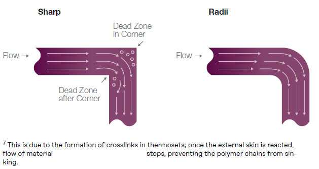
Uniform thickness throughout the part minimizes thermal gradients, which promotes even curing. Smooth transitions avoid abrupt mass differences and disruptions in the flow of material around corners which can lead to “dead zones” in the melt (illustrated later in Figure 8). Dead zones can cause filling problems and trap gas.
Sharp differences in mass lead to differential curing and internal shrink stresses that may not be visible on the molded ETS part. In general, engineering thermoplastics exhibit visible sink marks where there are “accumulated mass” or mass difference issues, engineering thermosets do not.
Faithfully applying the “uniform thickness − smooth transition” principle can prevent many design related part problems.
Radii
Recommended radii:
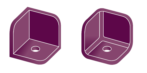
0.2 – 0.5 x wall thickness for inside fillet; 1.2 – 1.5 x wall thickness for outside corner radius
Sharp corners should be avoided. External corners are prone to chipping due to the brittle nature of most engineering thermosets. Internal corners are stress concentrators and locations for mechanical failures, which makes fillet radii at wall junctions particularly critical. Sharp corners also disrupt polymer melt flow during processing.
Figure 1 illustrates schematically how the polymer melt transitioning around a sharp corner exhibits dead spots in its flow (left) but transitions smoothly with the proper radius on the (right). Dead spots, as mentioned previously, can result in poor packing, trapped gas and the defects associated with those issues.
This is due to the formation of crosslinks in thermosets; once the external skin is reacted, flow of material stops, preventing the polymer chains from sinking.
Figure 2 shows corner sections of two parts. The one on the left is poorly designed with no radii at the wall intersections, while the one on the right is properly designed with radii on both the inside (fillet) and outside (corner).
Draft
Recommended draft:
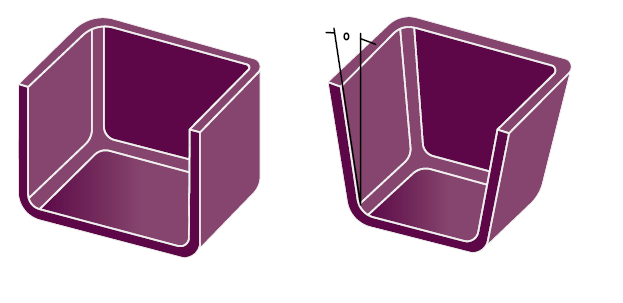
1.5° – 2.5°
Engineering thermosets exhibit little mold shrinkage but still require some draft on features that have depth (walls, ribs, gussets, bosses & stand-offs) in order for the part to be removed from the tool post cure. The lower end of the recommended range, 1.5°, is appropriate for highly filled, low shrink grades, and the higher end 2.5° for higher shrink grades. The general rule of thumb for textured surfaces is to add 1 – 2°. It is possible to successfully mold parts with lower draft, but it is not good practice to go below 0.5°.
Figure 1 shows corner sections of two parts. The one on the left is poorly designed with no draft the wall intersections, while the one on the right is properly designed with draft on all wall sections.
Dimensions
Recommended dimensions:
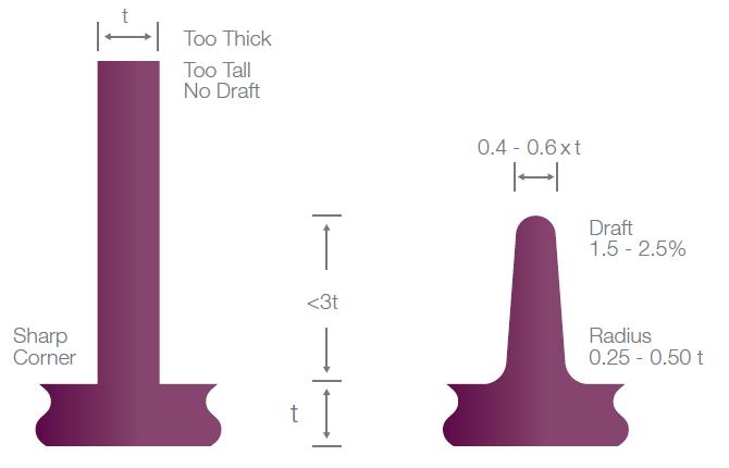
Width: 0.4 – 0.6 x wall section thickness (include draft) Height: < 3 x wall section thickness
Minimum spacing: 2 x wall section thickness
Figure 1 below shows a cross section of two ribs. The one on the left is too tall, too thick has no radii or draft. The rib on the right is shown with recommended dimensions, radii and draft.
Ribs and gussets (or buttresses) can be used to support part features such as a wall, boss or stand-off. They can also be used to direct melt flow during processing or to allow removal or “coring out” of material from thick sections to minimize cure time and prevent warpage.
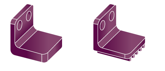
Figure 2 shows a molded flange designed two ways. The one on the left has a thick base tab that uses more material than necessary. This lengthens cure time and can cause warpage due to shrink stresses. The flange on the right shows how ribs can be employed to remove or “core out” material without compromising part strength. This design will use less material, cure faster and more evenly and will be less likely to warp
Bosses
Recommended dimensions:
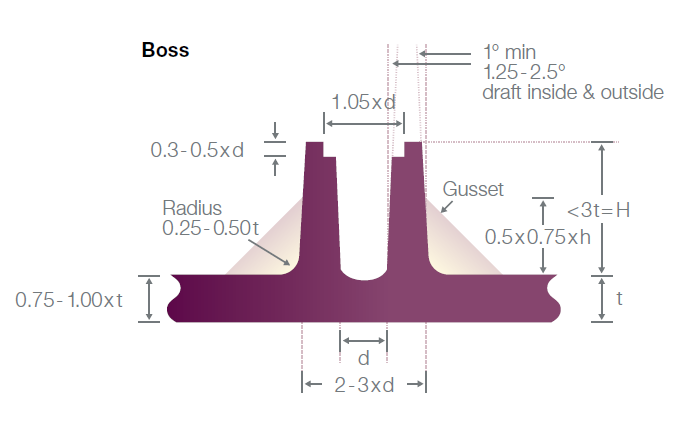
2-3 x diameter of hole (include draft) Height < 3 x wall section thickness
Figure 1 shows the cross section of a boss designed to recommended dimensions and supported by gussets. The diameter in the case of bosses is driven by the diameter of the hole. While no explicit limitations are cited, a practical limitation for the hole diameter is the thickness of the wall section the boss is attached to.
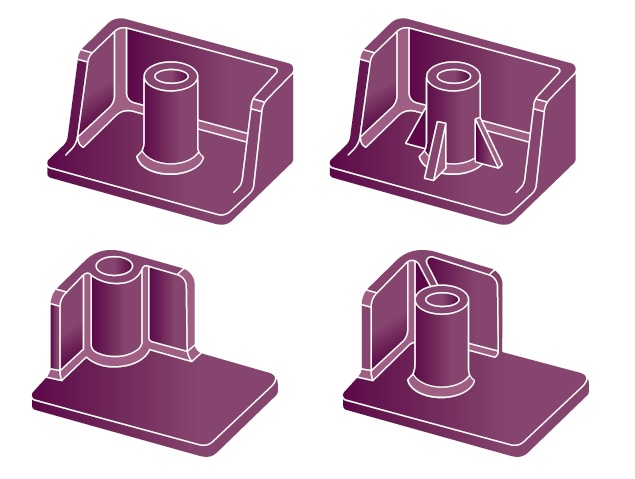
Figure 2 shows different options for boss designs in a part. On the upper left part, the boss is free standing without any support. This is a mechanically weak design but can be improved by supporting the boss with gussets as shown in the part on the upper right.
The boss in the part on the lower left is mechanically strong. But, while this type of design looks good in a CAD model, it usually results in processing problems. Extra material mass at the wall intersections and a challenging melt flow path leads to shrinkage stresses, voids, and depending on how it is filled, knitlines. It is better to offset the boss from the wall and support it with a rib as shown in the part on the lower right. The best option would be to surround the boss with three or four symmetrically located gussets.