
Shaping the Perfect Part: Mold Design Recommendations
The table (Download) contains general mold design recommendations. These are intended as “best practice” guidelines applicable for all molding compounds. Successful commercial parts have been produced in molds that are exceptions to these guidelines. Contact your Bakelite Synthetics Bakelite® product technical representative to determine what is possible for your specific application.
Complex parts will likely require compromise on one or more design recommendation. Trade-offs are inevitable, but certain recommendations should be given greater consideration than others. Minimal draft angle, minimal fillet radii on inside corners, and adequate venting are three that should be incorporated in every part and tool design.
Finally, though it has not been mentioned explicitly, close to attention should be paid to the material shrinkage rate used in the design. This should correspond to the specific material grade being used. Incorrect shrinkage is a frequent cause of tooling problems.
Runners
Example:
Main cross section: 0.25” – 0.31” x 0.125” (6.4 – 7.9 mm x 3.2 mm) Secondary cross section: 0.125” x 0.094” (3.2 mm x 2.39 mm)
Full round runners are the optimal geometry transporting the largest volume for the least surface area. Practically they are more work to machine. To form the full round runner, half round runners need to be machined on each surface of two mating plates (parting line in the middle). Trapezoidal cross sections are almost as efficient as a full round runner but need only to be machined in one plate.
Gating
Example dimensions:
General Purpose: 0.080”- 0.100” x 0.015” – 0.020” (2.00 – 2.54 mm x 0.38 – 0.51 mm) Mineral filled: 0.125” x 0.030” (3.18 mm x 0.76 mm)
Glass filled phenolic: 0.500” x 0.125 (12.7 mm x 3.18 mm)
The dimensions in each case depend on part design, expected mold filling, number of cavities and part volume.
All types of gating is possible with engineering thermosets:
Sprue, tab, fan, pin and sub gates regardless of filer or reinforcement content.
The gate location, type and dimensions:
- > Controls material flow into the cavity
- > Determines level of shear the material experiences
- > Determines where knitlines will form
- > Determines flow path which impacts warpage
Material flowing into a thick section of a cavity through a gate that is too small can result in jetting or damage to reinforcing fibers. Location of the gate (or gates), type and size determines where melt fronts will impinge on each other forming knitlines. These knitlines form wherever two melt fronts moving in different directions contact each other. Knitlines are always weak points. When two impinge on each other the degree to which they are able to mix before reacting determines how strong the knitline will be (it is always less than 100%).
Moldflow analysis is an important tool in this aspect of design. Being able to simulate flow through different gate styles sizes and locations allows a designer to optimize how best to fill the part.
Tool Steel
Example:
Cavities D2, M333 (or equivalent), H13 or S7, mold bases P20
Glass reinforced and mineral filled phenolic grades are highly abrasive. Production tooling for these materials should have cavities made of high chrome hardened tool steel; D2, M333 or equivalent hardened to HRC 48 – 52 are preferred. Other steels, such as hardened to HRC 44 – 48, or S7 hardened to HRC 50 – 52, can be used and either hard chrome plated or plasma nitrited for improved wear and corrosion resistance. Critical wear areas of production tools, such as gates, can be made with hardened inserts to allow easy replacement.
Standard mold bases commercially available from a number of suppliers — such as DME division of Milacron, Superior Die Set Corp, Mold Base Industries and others —
in a range of standard sizes and configurations can be used, or custom bases can be designed and built. The recommended steel type is P20 (No 3) prehardened to HRC 28 – 30, 4130 (No 2) can also be used, but is softer and will not have the same durability.
Molds for prototyping or short production runs can be made from soft carbon steel and hardened, or, preferably, machined from P20 prehardened to HRC 28 – 30.
Venting
Example:
Cavity vents: 0.0007” – 0.0050” (0.018 mm – 0.127 mm) depth, minimum width 0.125” (3.2 mm)
Ejector pin vents: 0.0007” (0.018 mm)
Melts push process gasses ahead of the flow front. Parting line vents generally should be located opposite the gate in the cavity in such a manner to allow gasses to escape during filling and curing of the engineering thermoset. Additional venting in other locations is often necessary.
Venting can be accomplished by reliefs cut into the tooling that allows for gasses to escape when the tool is closed and by opening the mold to degas during the filling and curing cycle. Both are effective and can be used separately or together.
Ejector pin vents can be an elegant solution to a trapped gas problem. These should be approached with caution, however. Vents that are too deep result in flash.
Heaters / Heat Design
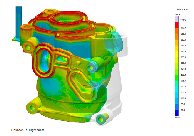
Even heating in the mold is critical to achieving uniform curing of ETS resins.
Electric cartridge heaters are efficient, cost effective and a good source for rapid concentrated heating. Their temperature control is adequate for small parts and multi cavity molds.
Thermal management in tooling for larger complex parts is more challenging with cartridge style heaters. For these applications, circulating fluid provides the most uniform heat and temperature control. The mass of fluid moving through the tool levels out temperature gradients and not only transports heat in, but transports excess heat out too.
Either hot oil or steam systems can be used. Oil is messy but can be operated at low pressures relative to steam which will require 225 – 350 psi (15 – 25 bar) to reach the required temperatures of 320 – 375 °F (160 – 190 °C).